
- Fri 05 April 2019
- research
- Trevor Metz
- #bikes, #engineering, #controller implementation, #arduino
This blog post has been updated in a newer blog post. Please see the updated version of this blog post for the most up to date information.
1.0 Introduction
The overall goal of this project is to design and implement a control system for an instrumented ebike used in bicycle handling experimentation. A previous blog post found here
outlines the design and analysis of a PID controller that meets the steady state error goal of +/- 0.1m/s. This blog post tells the story of how the designed PID controller was implemented on the instrumented ebike using an Arduino Nano.
2.0 System Operation & Functionality
The implementation of the PID controller on the electric bike was fundamentally informed by the interactions that the user would have with the system. A typical user interaction with the system is outlined in Figure 1 below.
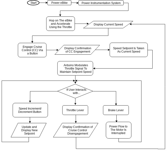
Figure 1. A typical user interaction with the system.
This user interaction flowchart was used to help better understand the problem and sculpt the concept for the hardware and software design of the speed control system.
3.0 System Architecture
3.1 Control Architecture
The control architecture is a simple feedback design that computes the error between a user defined setpoint and compares it to the speed of the ebike as measured via a DC generator wheel speed sensor (more on this in section 5.2). Figure 2, shows how this error is inputted to the control algorithm encoded in the Arduino Nano resulting in an output variable used to control the speed of the ebike.

Figure 2. Control architecture.
3.2 Physical Architecture
At the heart of the control system’s physical architecture is its integration into the existing instrumented ebike platform. Figure 3, below, shows this integration by highlighting the input/output and geometric relationships between existing components of the ebike and the additional control system components.
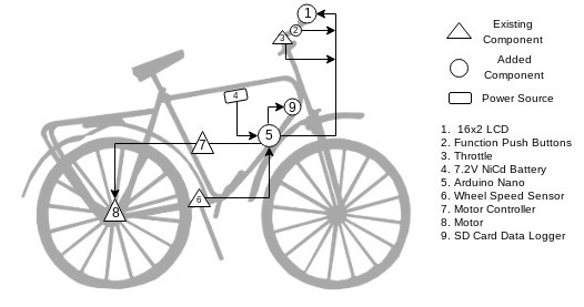
Figure 3. Geometric layout of the system components showing relative size, location, information flow, and type of each component. Components called out with a triangle are existing components on the ebike. Components called out with a circle are components that are introduced to the ebike system to implement the controller.
The fundamental interaction between the control system and the existing ebike powertrain system occurs at the interface between the Arduino nano and the ebike motor controller. While the cruise control is engaged, the function of the Arduino is to take control of the throttle signal away from the user and pass it through the control algorithm before sending it to the motor controller. When the cruise control is disengaged, the Arduino simply reads the user commanded throttle position and passes it directly to the motor controller. Figure 4, below, graphically shows this interaction.

Figure 4. Schematic showing the Arduino’s function as a throttle emulator.
4.0 Software
The control system software was written in C using the Arduino IDE. Based on user inputs from two momentary pushbuttons, the software decides whether or not to pass the throttle signal as an output or compute a throttle output based on the PID controller. The software also updates the user on the current status of the system via an LCD and logs diagnostic information to an SD card.
Figure 5, below, shows the logic flow of the code.
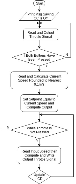
Figure 5. Code logic flowchart.
The software, and more details about it, can be found on the Laboratorium’s Github repository found here.
4.1 Code Libraries
The continuous time PID controller derived in part one of this blog post series was digitized on the Arduino Nano using Brett Beauregard’s PID_v1 library (found here). This library was developed by Brett to implement PID controllers on an Arduino microcontroller.
Brett’s library was chosen to implement the PID controller because of its many robust features such as Derivative Kick and Initialization. Additionally, this library contains fantastic documentation which can be found here.
To avoid slowing the code’s main loop, interrupts were used to manage the change in setpoint brought on by a press of the speed increment decrement buttons. Using interrupts free’s up the Arduino’s processor from having to check whether or not there’s been a button press on every loop iteration. Instead, the processor reacts to pin changes and interrupts the execution of the main code to perform the function tied to the interrupt pin. However, the Arduino Nano only has a limited number of pins that can be used as interrupts. A library, written by GreyGnome (found here), enables the use of interrupts on any pin of the Arduino Nano. This library was used to free up pin real estate for the many components that are wired up to the Arduino.
5.0 Hardware Hook Up and Design
5.1 Instrumented Ebike Platform
Jason Moore, the lab’s PI, originally began constructing the instrumented ebike platform in 2009 from a large Surly single speed off road steel frame bicycle converted to an ebike with a conversion kit sold by Amped Bikes. The Amped Bikes kit consists of a brushless direct drive hub motor driven by a motor controller and a 36V Li ion battery. More information on the build and the bike’s instrumentation system can be found in Jason’s dissertation found here.
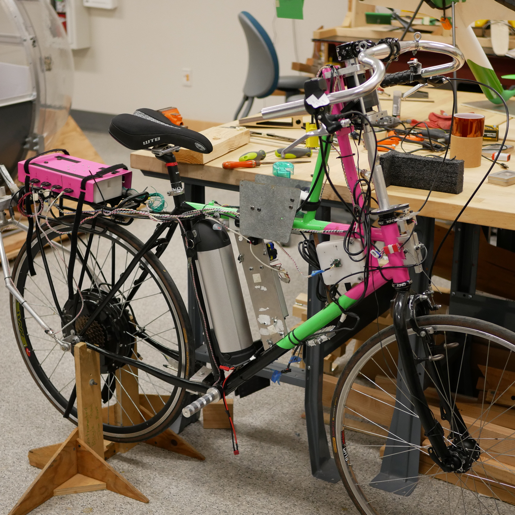
Figure 6. The instrumented ebike today.
5.2 Electrical Hook Up
The electrical components of the control system revolve around an Arduino Nano which is used to process inputs and outputs to human interface hardware, actuators, and logging hardware. Table 1, below, shows a complete list of the hardware used in this build.
| Component Name | Details | Function |
|---|---|---|
| Arduino Nano | ATmega328P Processor | Main Processor |
| Wheel Speed Sensor | DC generator in contact with rear tire (Click here for more information) | Control Loop Input |
| Voltage Divider | Used to step down wheel speed sensor voltage to a range measurable by the Arduino | Wheel Speed Sensor Signal Conditioning |
| Pushbuttons | Momentary pushbuttons to get user input | User Input |
| Battery | 7.2V NiCd | System Power |
| LCD | 16x2 character LCD | User Feedback |
| Motor Controller | Amped Bikes motor controller | Control Loop Output |
| SD Card Module | SPI SD card module for Arduino | Data Logging |
Figure 7, below, shows a Fritzing diagram of the electrical system.
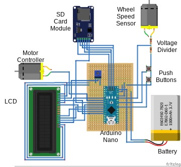
Figure 7. Fritzing diagram of control system electronics. Note that the motor controller is represented by a DC motor and the 7.2V NiCd battery is represented by a 1S LiPo battery.
The Arduino Nano and the voltage divider circuits were soldered to a small 3" x 1.1" piece of stripboard. Wires, braided 22AWG, were soldered to the stripboard to connect the external components to the Nano. Figure 8, below, shows the completed Arduino board.
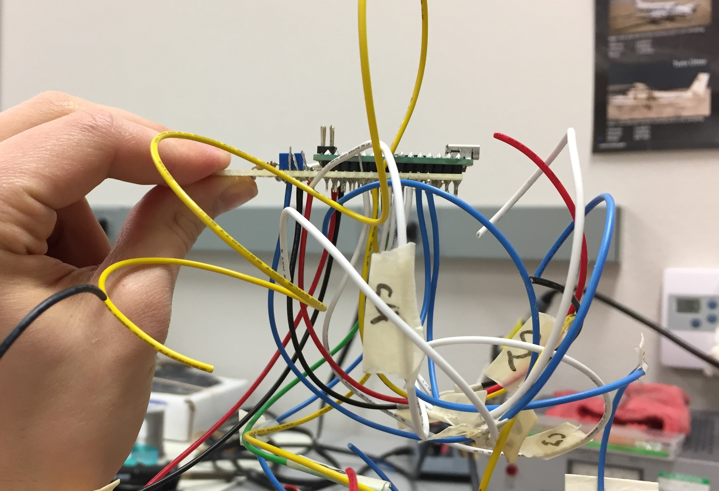
Figure 8. The Arduino board with wires attached.
With many of the components located on the handlebars, a majority of these wires were routed together along the top tube, up the head tube and stretched across to the handlebars. This task was facilitated using spiral wound cable housings, zip ties, and a 15 pin Molex connector. Once on the handlebars, wires were connected to header pins on the LCD and pushbuttons with Dupont connectors.
Rearward of the Arduino, T-tap wire splices were used to cleanly splice power signals from the NiCd battery above the Arduino near the top tube and from the wheel speed sensor near the bottom bracket.
5.3 Electronics Housings
Housings for the Arduino Nano, pushbuttons and LCD were designed and 3D printed to enclose the electrical components and mount them to the ebike. Figure 9, below, shows the CAD model design of the Arduino housing. The housing’s design includes pins for press fitting the Arduino stripboard to the mount. Slots on the sides and top of the housing allow for wires to exit towards their destinations on the ebike. Threaded inserts on the base are used to secure the top cover using M3 screws.
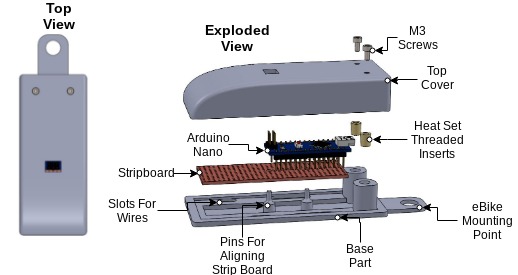
Figure 9. Arduino housing design.
This housing is clamped to the downtube of the ebike by a socket head screw as shown in Figure 10.
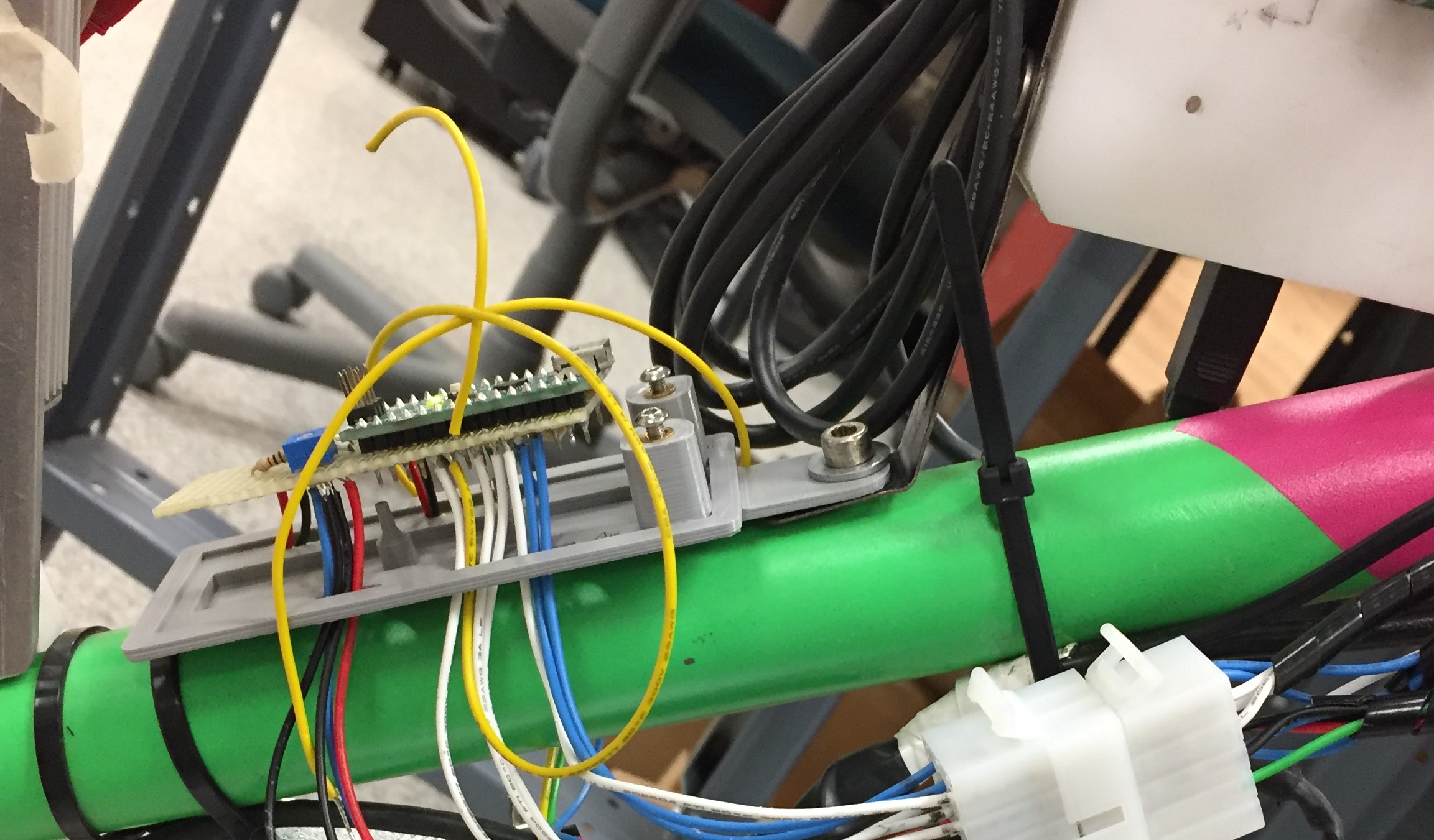
Figure 10. Arduino housing mounting point.
Both the LCD and button housings were 3D printed and designed to mount to the handlebars using a clamshell style mount used for securing GoPro cameras to bikes. Each mount had a pair of “bunny ears" designed to interface with the GoPro style mount. The LCD housing, shown in Figure 11 below, is a simple rectangular two-piece enclosure joined by button head screws.
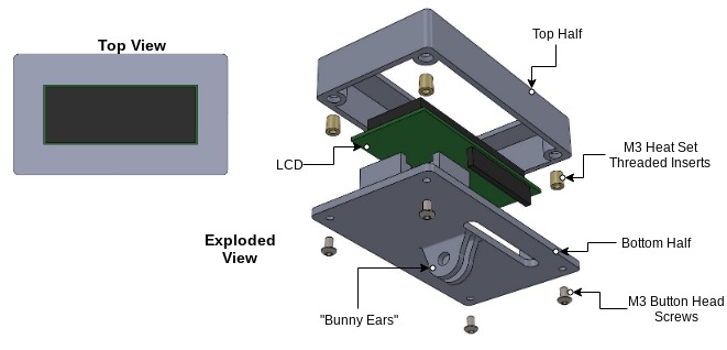
Figure 11. LCD housing design.
Similar to the LCD housing, the button housing is a two-piece, enclosure joined by screws. Inside the housing is a small piece of stripboard that the pushbuttons are soldered to. To make pressing the mini momentary pushbuttons more convenient for the user, larger button parts were 3D printed and offset from each mini momentary pushbutton using a compression spring as shown in Figure 12 below.
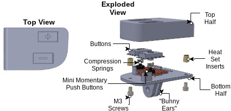
Figure 12. Button housing design.
As shown in Figure 13, the button housing is mounted on right side of the handlebars near the throttle and brake lever for convenient access.
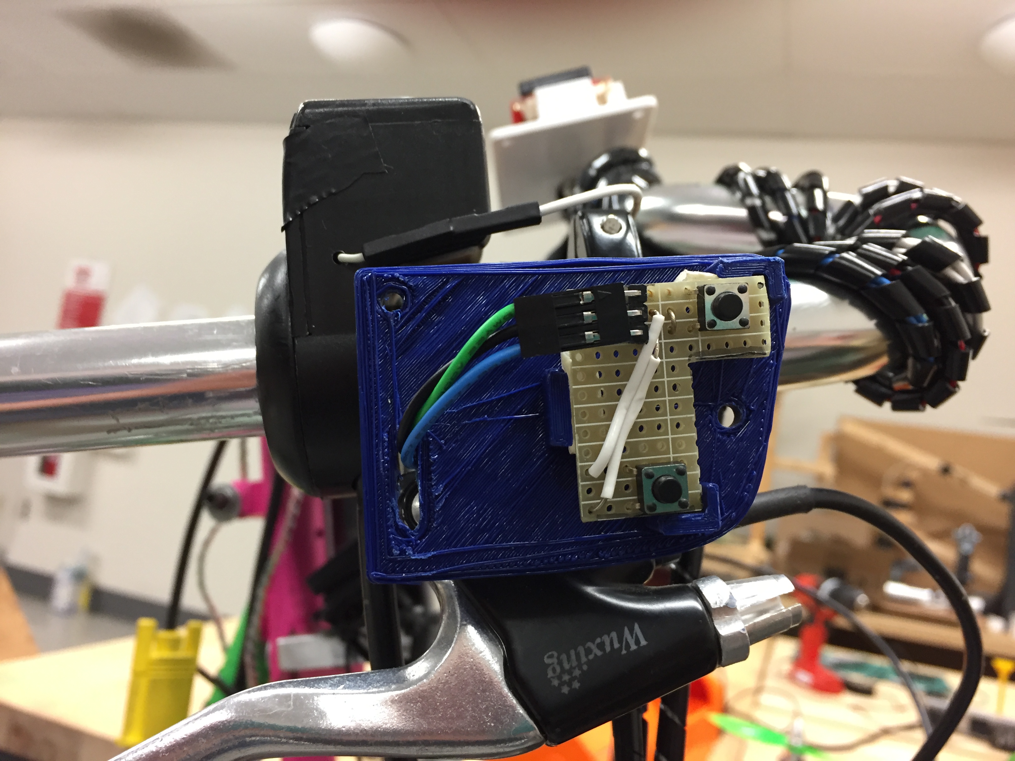
Figure 13. Button housing position on the handlebars.
6.0 Bill of Materials
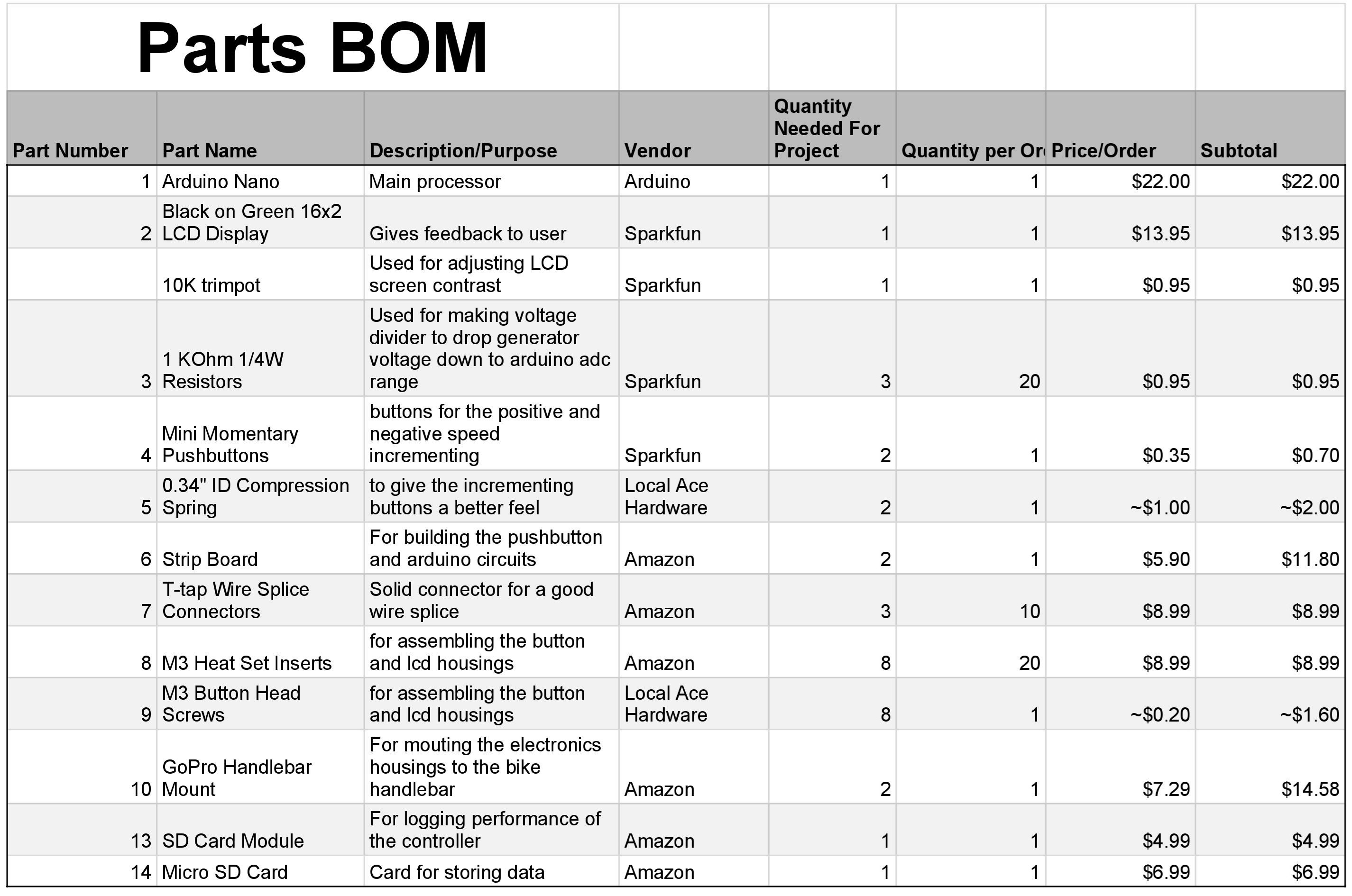
Table 2. Bill of materials (BOM) showing each part of project, where it was purchased, what quantity was purchased and its cost.
7.0 Lessons Learned and Suggested Improvements
Throughout the process of implementing this controller, I learned some helpful lessons when it comes to designing electronics housings and doing electrical hookups.
Some lessons learned include the following:
- It is important to account for the minimum bend radius of each wire inside of an electrical enclosure
- It is important to follow best practices when designing for heat set threaded inserts
- Iteration is required in order to achieve a design intent when 3D printing
- Test the assembly and function of electrical connections on scrap wire before commiting changes
Throughout the implementation of this design, I've made note of some improvements to the system's design that could be made. I have listed these below:
- A larger momentary pushbutton could be used to reduce the complexity of the button housing and improve its functionality
- Use a display that communicates via the SPI protocol to reduce the number of wires used
- For the Arduino board, use a custom PCB to increase the robustness of the board
8.0 Acknowledgements
I would like to thank Nicholas Chan for writing the camera gimbal software that my speed control software is based off of. I’d also like to thank Brett Beuaregard for writing the PID library and it’s excellent documentation that is the heart of the speed control software. Finally, I’d like to thank Jason Moore for his support and mentorship throughout this project.
Stay tuned for part three of this series: Testing and Validation